 |
|
 |
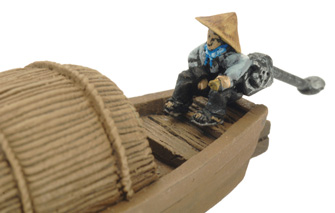 |
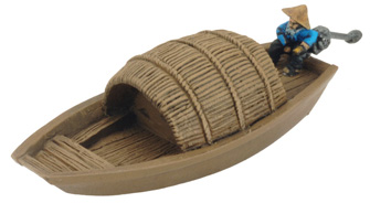
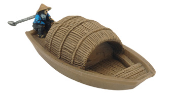
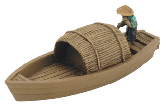
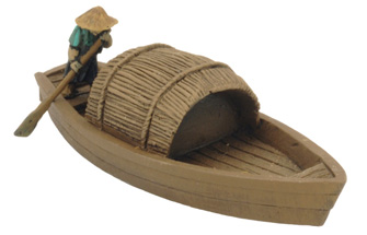
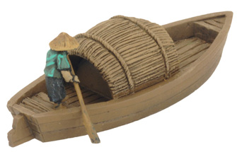
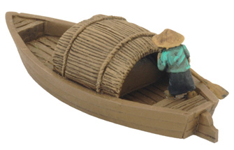
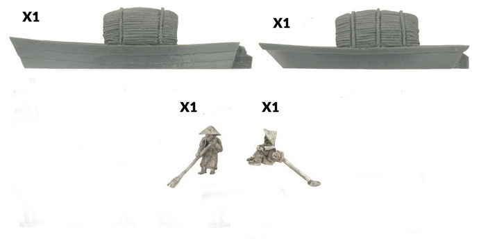
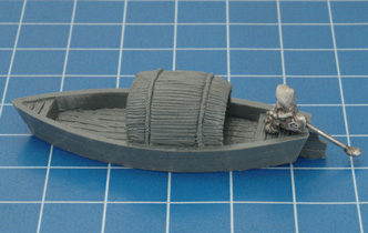
Contains two Sampan boats and two crew figures
Free World forces in the Republic of Vietnam faced the day-to-day paranoia of dealing with a civilian population whose loyalties could not be guessed. Any man, woman, or child of the local populace could be working for the resistance, reporting on troop movements, providing false information, or sniping at the enemy. |
|
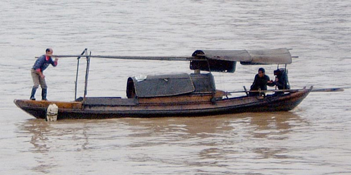
Sampan Boats |
| Sampans were shallow-draft boats generally used for transportation of goods or people, usually in rivers or coastal areas. It was unusual for a sampan to sail far from land as they did not have the means to survive rough weather. They strived in areas normal boats couldn’t easily sail in.
Designed by Evan Allen |
 |
 |
 |
 |
 |
 |
 |
 |
 |
|
Contents Contact the customer service team at [email protected] if you have any issues with any of the components. |
|
 |
|
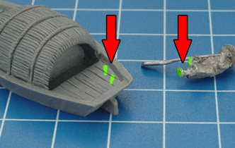
Assembling the Sampan Boats (VPA822) |
||
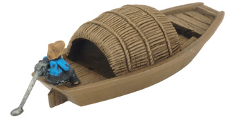
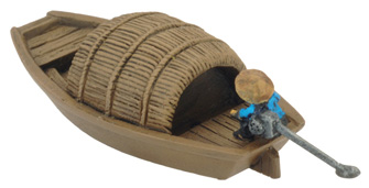
| When assembling your sampan boats you have the option of using a rower or an engine operator. Below I will show you how to add either one.
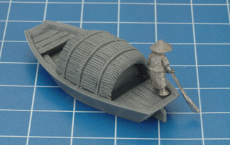
Rower. Glue the feet of the rower to the back right of your Sampan boat as shown below. |
||
| Tip: When assembling your models it’s always a good idea to dry fit your parts before glueing. | ||
 |
 |
|
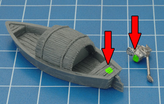
| Engine operator. Glue the bottom the the engine operator to the back of the boat. Don’t forget to dry fit! | ||
 |
 |
|
 |
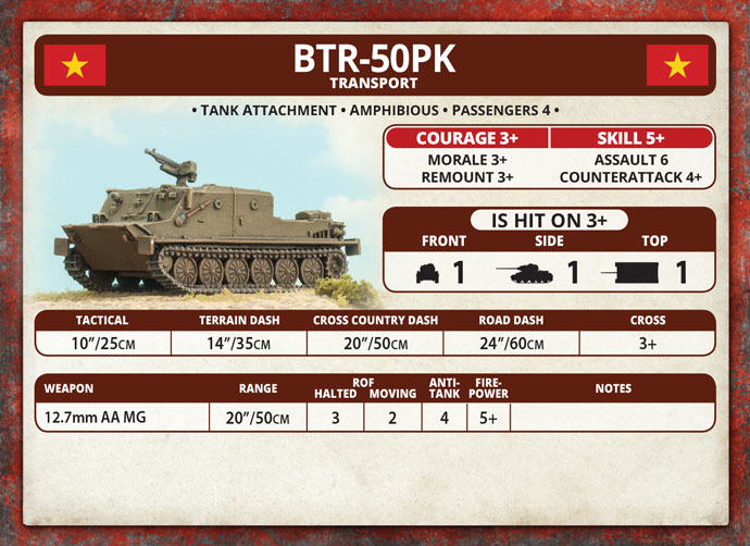
includes one BTR-50PK Armoured Personnel Carrier
The three companies of a North Vietnamese armoured battalions were often equipped with different types of tanks. At first this was due to a shortage of modern tanks, but later combinations of tanks, amphibious tanks, and armoured personnel carriers allowed a battalion to undertake whatever role was assigned it without further support. |
| Most armoured battalions include a đại đội cơ giới bộ binh (pronounced dai doy kur vay boh beeng), or mechanised infantry company. These operate Soviet BTR-50PK xe thiết giáp chở quân (pronounced ser tee-et harp chur kwun) armoured troop carriers. Their role is to use their mobility and armour to advance close behind the tanks, then dismount and assault on foot covered by fire from the tank’s guns. Their high proportion of B41 anti-tank weapons means that they can defend themselves if attacked by enemy tanks.Designed by Evan Allen Painted by Blake Coster |
 |
 |
| The BTR-50PK in ‘Nam | |
 |
|
") |
") |
| Most armoured battalions included a mechanised infantry company operating Soviet BTR-5OPK armoured troop carriers. Their role is to use their mobility and armour to advance close behind the tanks, then dismount and assault on foot covered by fire from the tank’s guns. | |
 |
 |
 |
 |
 |
 |
| Contents of the BTR-50PK Company Box Set |
| Contact the customer service team at [email protected] if you have any issues with any of the components. |
 |
| Description of Components |
| a. Tank commander sprue. b. Hatch sprue. c. .50cal AA MGs d. Mudguard sprues. |
e. Right-hand side tracks. f. Left-hand side tracks. g. Resin BTR-50PK hulls. |
| Assembling The BTR-50PK Follow the diagram below to assemble the BTR-50PK correctly. Tip: Use the figure of your choice from the tank commander sprue to identify the platoon command tank. |
|
Below: The assembly diagram for the BTR-50PK. |
 |
| PAVN Tank Painting Guide |
 |
 |
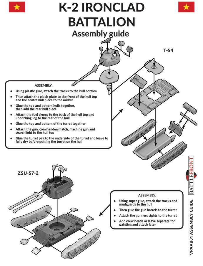
includes one ZSU-57-2 SP Anti-aircraft gun and one PAVN head sprue
The ZSU-57-2 was a Soviet-built self-propelled anti-aircraft gun that first came into service with the Red Army in 1955. The acronym ZSU stands for Zenitnaya Samokhodnaya Ustanovka, which when translated means anti-aircraft self-propelled mount; 57 designates the calibre of the weapons and 2 states the number of gun barrels. Check out the ZSU-57-2 SP Anti-aircraft Gun in the online store here… |
| Built on the chassis of the T-54 tank, the twin S-68 57mm cannons were mounted in an open-topped turret which only offered the crew inside a minimum level of armour protection. Manned by a crew of six (driver, commander, gunner, dedicated sight adjuster and a pair of loaders), the ZSU-57-2 was limited to only engaging aircraft that the crew could actually see. Once an aircraft was spotted, the sight adjustor had to correctly calibrate the gun sight before the target could be engaged; making the vehicle virtually useless during nighttime operations. |
 |
 |
| The war in Vietnam was the first recorded service for the ZSU-57-2 in a combat zone. But the North Vietnamese quickly learnt that the ZSU-57-2 was just as effective in providing fire support for infantry attacks as it was sweeping the air of enemy aircraft. Designed by Evan Allen Painted by Blake Coster |
|
 |
 |
| The ZSU-57-2 in ‘Nam | |
 |
|
 |
 |
 |
 |
| The ZSU-57-2 anti-aircraft tank is the chassis of a T-54 battle tank mounting twin 57mm anti-aircraft guns in an open-topped turret. Its rate of fire makes it deadly to aircraft and helicopters, while its high-velocity, long-barrelled guns punch through light armour with ease. | |
 |
 |
| Contents of the ZSU-57-2 Blister |
 |
| Contact the customer service team at [email protected] if you have any issues with any of the components. |
| Assembling The ZSU-57-2 Follow the diagram to the below to correctly assemble the ZSU-57-2. |
 |
| Step 1. Begin assembly with the tracks.
Tip: Each track is stamped with the letter ‘R’ or ‘L’ to indicate correct orientation. |
Step 2. Attach the tracks to the resin hull. Tip: When referring to left or right-hand side in regards to a Flames Of War miniature, the orientation is determined as if looking at the vehicle from the rear. |
|
 Ironclad Company (VPABX03)") |
 Ironclad Company (VPABX03)") |
 Ironclad Company (VPABX03)") |
| Step 3. Next, attach the mudguards to the front and rear of the hull.
Tip: The mudguards are generic so can be used in anywhere on the hull. |
Below: Both front mudguards attached to the hull. | |
 Ironclad Company (VPABX03)") |
 Ironclad Company (VPABX03)") |
 Ironclad Company (VPABX03)") |
| Step 4. Attach the mudguards to the rear of the hull. | Below: Both rear mudguards attached to the hull. | |
 Ironclad Company (VPABX03)") |
 Ironclad Company (VPABX03)") |
 Ironclad Company (VPABX03)") |
| Step 5. Next, attach the main gun to the front of the turret. | Below: The main gun attached to the front of the turret. |
 Ironclad Company (VPABX03)") |
 Ironclad Company (VPABX03)") |
| Step 6. Attach the turret hatch to the top of the turret. | Step 7. Finally, attach a AA machine-gun the rear of the turret. | ||
 Ironclad Company (VPABX03)") |
 Ironclad Company (VPABX03)") |
 Ironclad Company (VPABX03)") |
 Ironclad Company (VPABX03)") |
| Adding A Tank Commander | |||
| Step 1. Attach the commander’s hatch to the turret in the open position. | Step 2. Add the tank commander figure of your choice. | Tip: It may be necessary to reposition the AA machine-gun to accommodate the tank commander and the open hatch. | |
 Ironclad Company (VPABX03)") |
 Ironclad Company (VPABX03)") |
 Ironclad Company (VPABX03)") |
 Ironclad Company (VPABX03)") |
| Below: The fully-assembled K-3 (PT-76) with and without a commander. |
 Ironclad Company (VPABX03)") |
 Ironclad Company (VPABX03)") |
| PAVN Tank Painting Guide | |
 Ironclad Company (VPABX03)") |
|
| Step 1. Begin assembly by attaching the tracks to the hull of the Centurion.
Note: Each track has been keyed to correspond with a particular side of the hull; this aids in ensuring the correct orientation of the tracks when assembling the miniature. |
| Below: The correct alignment for the left-hand side track. | Below: The correct alignment for the right-hand side track. | Below: The left-hand side track attached to the hull. |
") |
") |
") |
| Tip: When referring to left or right-hand side in regards to a Flames Of War miniature, the orientation is determined as if looking at the vehicle from the rear. | ||
| Below: The right-hand side track attached to the hull. | Step 2. Next, attach the front mudguard to the front of each track. | Below: The left-hand side front mudguard attached to the track. |
") |
") |
") |
| Below: The right-hand side front mudguard attached to the track. | Below: Both front mudguards successfully attached to the tracks. | Step 3. Next, attach the rear mudguards. |
") |
") |
") |
| Note: The left-hand side rear muguards has a small cylinder on it. | Below: The right-hand side rear mudguard has a plane surface. See the examples below. | |
") |
") |
") |
| Below: Both rear mudguards successfully attached to the tracks. | Step 4. Next, attach the additional fuel tank to the rear of the hull. | |
") |
") |
") |
| Step 5. Attach the main gun to the front of the turret. | Step 6. Next, attach the turret stowage rack to the rear of the turret. | ||
") |
") |
") |
") |
| Step 7. Attach the loader’s hatch to the top of the turret. | Step 8. Attach the commander’s cupola to the top of the turret. | ||
") |
") |
") |
") |
| Step 9. Attach the .30 cal AA MG to the mount on the cupola. | Below: The fully-assembled Centurion ready for the painting table. | |
") |
") |
") |
| Adding A Tank Commander | |||
| Step 1. Replaced the closed commander’s cupola with the open cupola. | Step 2. Add a tank commander figure to the open cupola. | Tip: The .30 cal AA MG will need to be attached on a slightly different angle with a tank commander. | Below: The fully-assembled Centurion Mark 5 complete with tank commander. |
") |
") |
") |
") |
| ANZAC Vehicle Painting Guide |
") |
| Step 1. Begin assembly of the M41A3 Walker Bulldog by attaching the tracks.
Tip: Ensure that the drive sprocket is towards the rear of the vehicle. |
Step 2. Next, attach the 76mm main gun to the front of the turret. | ||
") |
") |
") |
") |
| Below: The 76mm main gun has been keyed to match the front of the turret. | Below: The 76mm main gun correctly attached to the turret of the M41A3 Walker Bulldog. | Step 3. Next, attach the commander’s cupola to the top of the turret. |
") |
") |
") |
| Below: The commander’s cupola correctly attached to the turret of the M41A3 Walker Bulldog. | Step 4. With the commander’s cupola in place, it’s time to add the loader’s hatch to the opposite side of the turret. | Below: The loader’s hatch correctly attached to the turret of the M41A3 Walker Bulldog. |
") |
") |
") |
| Step 5. Finally, attach the .50 cal AA MG to the mount found near the commander’s cupola. | Below: The .50 cal AA MG correctly attached to the turret of the M41A3 Walker Bulldog. | Below: With the .50 cal AA MG in place, the M41A3 Walker Bulldog is ready for the painting table. |
") |
") |
") |
| Adding a Tank Commander | ||
| Step 1. Replace the closed cupola with the open cupola included on the hatch sprue. | Step 2. Add a commander into the open cupola. | Below: The M41A3 Walker Bulldog fully-assembled with tank commander. | |
") |
") |
") |
") |
| a. 1x M113 Driver head sprue. b. 2x M113 T50 turrets. c. 2x M113 T50 main guns. d. 2x M113 T50 turret hatches. |
e. 2x M113 M74C turrets. f. 2x M114 M74C hatches. g. 4x Vehicle commander figures. |
| Assembling The M113 T50 Turret | |
| Step 1. Attach the main gun to the front of the turret ensuring that the shorter .30 cal MG is on the right-hand side. | Step 2. Next, attach the hatch to the top of the turret. | |
| Tip: When referring to left or right-hand side in regards to a Flames Of War miniature, the orientation is determined as if looking at the vehicle from the rear. | ||
") |
") |
") |
| Below: The hatch attached to the turret. | Step 3. The T50 turret simply replaces the weapons turret of the stock M113. | Below: The fully assembled M1113 complete with T50 turret. | |
") |
") |
") |
") |
| Adding A Vehicle Commander | ||
| Step 1.Attach the hatch in an open position. | Step 2. Add the vehicle commander into the open hatch. | Below: The M113 with T50 turret fully assembled complete with vehicle commander. |
") |
") |
") |
| Assembling The M113 M74C Turret | ||||
| Step 1. Attach the M74C turret hatch to the rear of the turret. | Step 2. The M74C turret simply replaces the weapons turret of the stock M113. | Below: The fully assembled M1113 complete with M74C turret. | ||
") |
") |
") |
") |
") |
| Adding A Vehicle Commander | ||
| Step 1.Attach the hatch in an open position. | Step 2. Add the vehicle commander into the open hatch. | Below: The M113 with M74C0 turret fully assembled complete with vehicle commander. |
") |
") |
") |
| Step 1. Begin by attaching the FSV deck to the hull of the M113. | Step 2. Attach the driver’s hatch to the FSV deck. | |
") |
") |
") |
| Below: The driver’s hatch attached to the FSV deck. | Below: The M113 FSV hull fully assembled. | Step 3. Next, attach the main gun to the front of the turret. |
") |
") |
") |
| Below: The main gun attached to the turret. | Step 4. Next, attach the hatches to the top of the turret. | |
") |
") |
") |
| Below: Adding the hatches to the top of the turret. | Below: The fully assembled M113 FSV. | |
") |
") |
") |
| Adding A Vehicle Commander
Step 1.Attach the hatch in an open position. |
Step 2. Add the vehicle commander into the open hatch. | Below: The M113 FSV fully assembled complete with vehicle commander. | |
") |
") |
") |
") |