Posted on

Patrol Boat (VUSBX12) Spotlight


PBR (Patrol Boat, Riverine x2) (VUSBX12) 
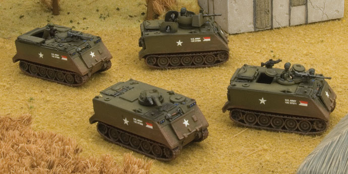
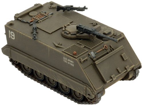
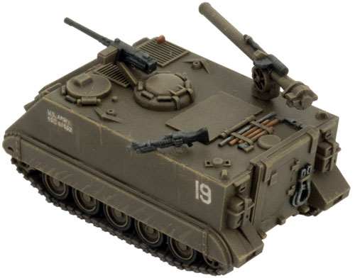
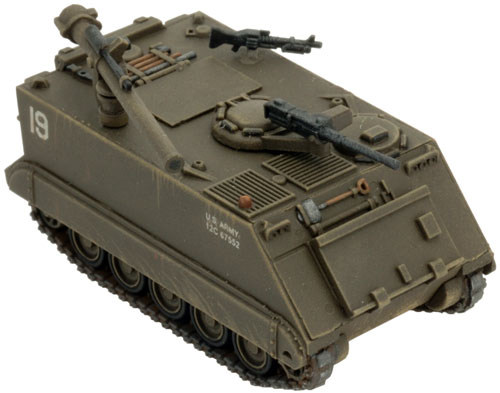
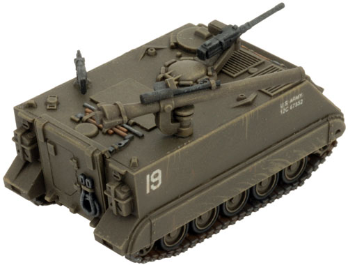
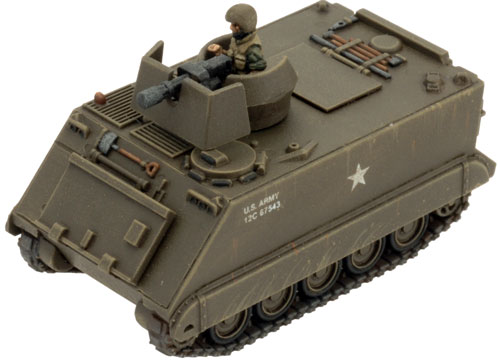
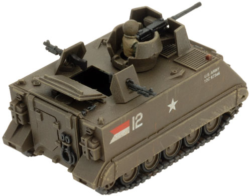
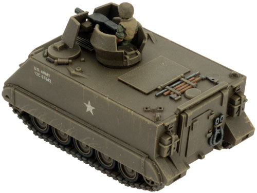
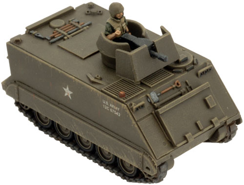
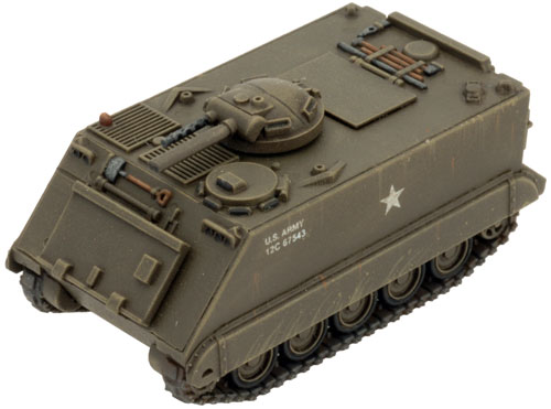
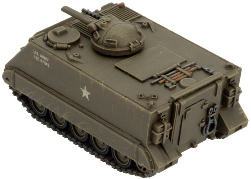
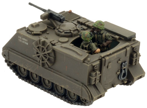
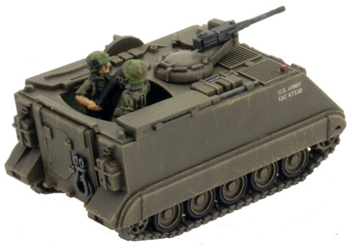
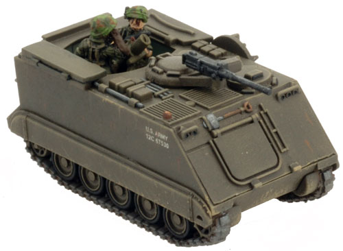
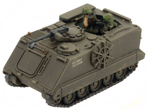
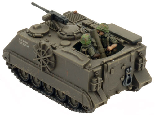
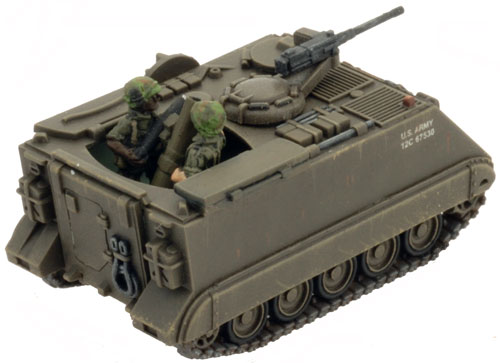
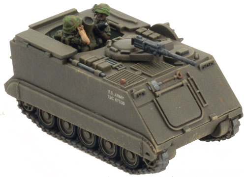
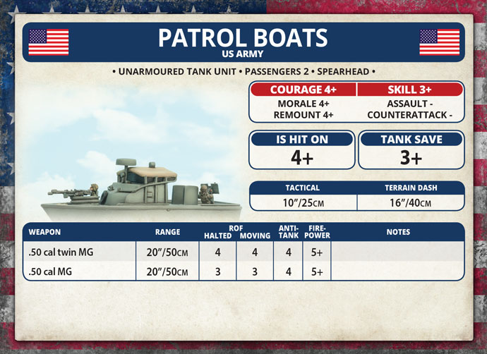
The Patrol Boat, River or PBR, was a small rigid-hulled patrol boat that was the mainstay of Operation Game Warden. PBRs did not usually operate with the Mobile Riverine Force; their mission was to interdict illicit waterway traffic and provide intelligence to the navy. Occasionally, this mission would overlap with the Mobile Riverine Force’s mission and the two would cooperate.

Check out the Patrol Boat in the online store here…

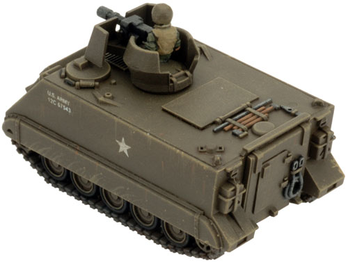
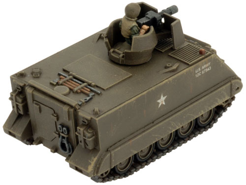
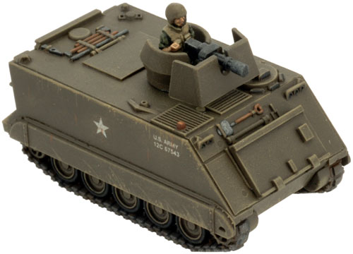
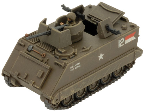
The PBR was usually manned by a 4-man crew. Typically, a First Class Petty Officer served as boat captain, with a gunner’s mate, an engineman and a seaman on board. Each crewman was cross-trained in each other’s job in case one became unable to carry out his duties. Generally, PBRs operated in pairs under the command of a patrol officer, who rode on one of the boats.

Designed by Evan Allen
Painted by Aaron Mathie

PBR (Patrol Boat, Riverine x2) (VUSBX12)

The PBR (Patrol Boat, River) Mk II PBR

Length:

31’ 11” (9.8m)
Beam: 11’ 7” (3.5m)
Draft: 2’ (60cm)
Displacement: 16000lb (7.25tonnes)
Speed: 28 knots (52km/h)
Crew: 4

The PBR in ‘Nam

 
PBR (Patrol Boat, Riverine x2) (VUSBX12) PBR (Patrol Boat, Riverine x2) (VUSBX12)
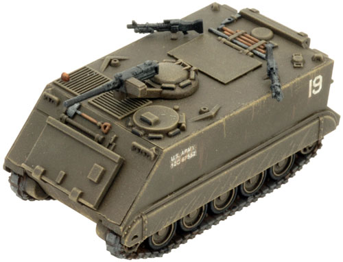
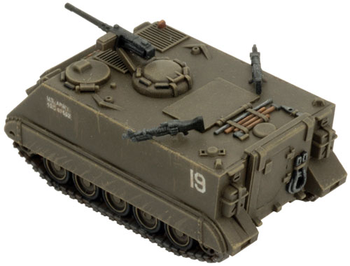
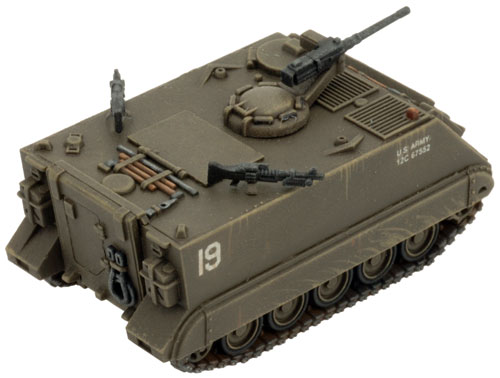
With a shallow-draught fibreglass hull and water jet drive, the PBR could operate in the shallow, weed-choked rivers of the Mekong Delta. The dual 180hp pump-jet drives, which could be pivoted to reverse direction, made the boat extremely fast and nimble. PBRs did not have much in the way of armour protection – just some shielding for the .50-cal machine guns and upright steel armour plates in the midships. Instead, the boats were designed to rely on acceleration and maneuverability to get out of trouble.
PBR (Patrol Boat, Riverine x2) (VUSBX12) PBR (Patrol Boat, Riverine x2) (VUSBX12)

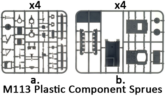
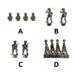
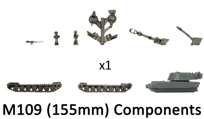
Contents of the PBR box

Contact the customer service team at [email protected] if you have any issues with any of the components.
PBR (Patrol Boat, Riverine x2) (VUSBX12)
Posted on

M114 155mm Firebase Assembly Guide


155mm Field Artillery Battery (VUSBX10) The M114A1 155mm Howitzer Crew
Description of Components

a. 2x Standing figures bending over.
b. 2x Standing figures with hands on hips.
c. 2x Loader figures holding shell.
d. 2x Standing figures covering ears.
e. 2x Standing figures with arm raised.
Assembling The M114A1 155mm Howitzer Crew
Simply arrange one of each figure type around each of the M114A1 155mm howitzer to taste. The M114A1 155mm howitzer and crew a modelled on the large six-hole bases provided in the box set.
155mm Field Artillery Battery (VUSBX10)
Description of Components
a. 4x Gun trail wheels.
b. 2x Gun shields / carriages.
c.
 2x Gun carriage stabilisers.
d. 2x Gun barrels.
e. 2x Gun trail legs.
f. 2x Gun trail spades.
155mm Field Artillery Battery (VUSBX10) The Bases
Description of Components
3x Large six-hole bases.
Assembling The M114A1 155mm Howitzer
Step 1. Begin assembly of the M114A1 155mm howitzer by attaching the spades to the end of the gun trail legs. Below: Both spades attached to the gun trail legs. Step 2. Next, attach the gun carriage wheels to the sides of the gun shield / carriage.
155mm Field Artillery Battery (VUSBX10) 155mm Field Artillery Battery (VUSBX10) 155mm Field Artillery Battery (VUSBX10) 155mm Field Artillery Battery (VUSBX10)
Below: Both gun carriage wheels successfully attached to the gun shield / carriage. Step 3. Next, its time to attach the gun trail legs. The back of the gun shield has been keyed to accept the gun trail legs. Below: Attaching the gun trail leg to the back of the gun shield.
155mm Field Artillery Battery (VUSBX10) 155mm Field Artillery Battery (VUSBX10) 155mm Field Artillery Battery (VUSBX10)
Below: Both gun trail legs successfully attached to the back of the gun shield. Step 4. Next, attach the gun carriage stabiliser to the underside of the gun shield.
155mm Field Artillery Battery (VUSBX10) 155mm Field Artillery Battery (VUSBX10) 155mm Field Artillery Battery (VUSBX10)
Below: The attached gun carriage stabiliser on the underside of the gun shield. Step 5. Finally, attach the gun barrel to the gun carriage.
155mm Field Artillery Battery (VUSBX10) 155mm Field Artillery Battery (VUSBX10) 155mm Field Artillery Battery (VUSBX10)
Below: The gun barrel attaches to the gun carriage just behind the recuperator cylinder. Below: With the gun barrel in place the M114A1 155mm howitzer is ready to be painted.
155mm Field Artillery Battery (VUSBX10) 155mm Field Artillery Battery (VUSBX10) 155mm Field Artillery Battery (VUSBX10)
Posted on

M114 155mm Firebase (VUSBX10) Spotlight


Includes one Gun section with three M114A1 155mm howitzers with crew & three Large six-hole bases.

Development of the 155mm howitzer M1 began during the late 1930s, when the United States Army determined it needed a new medium field artillery piece to replace the World War One vintage howitzer M1917.

Check out the 155mm Field Artillery Battery in the online store here…

The 155mm used separate loading ammunition comprised of four components: a projectile, a separate bagged propellant charge, a fuse and a primer. The propelling charge contained individual bags of powder, which could be reduced depending on the range of the target. The projectiles weighed 95lb each with the fuses placed in the base of the projectile after a ring used for shipping was removed. The primers were placed in the breech of the gun for firing. The 155mm howitzer typically fired 80% or more HE (high explosive) shells, however, it could also fire smoke or white phosphorus shells.

In 1962 the designation system for artillery changed and the 155mm howitzer became known as the M114A1 155mm howitzer. The change in designation didn’t detract from its performance in any way during the course of the conflict in Vietnam.

Gun designed by Evan Allen & Seth Nash
Crew designed by Evan Allen
Painted by Mark Hazell

The M114A1 155mm Howitzers
155mm Field Artillery Battery (VUSBX10) 155mm Field Artillery Battery (VUSBX10) 155mm Field Artillery Battery (VUSBX10)
The M114A1 155mm Howitzer in Flames Of War Vietnam
155mm Field Artillery Battery (VUSBX10) 155mm Field Artillery Battery (VUSBX10) 155mm Field Artillery Battery (VUSBX10)
Contact the customer service team at [email protected] if you have any issues with any of the components.
Posted on

105mm Field Artillery Battery Assemby


Description of Components
105mm Field Artillery Battery (VUSBX09) The M101A1 105mm Howitzer Crew
Description of Components

a. 2x Standing figures bending over.
b. 2x Loader figures holding shell.
c. 2x Loader figuers discarding spent shell case.
d. 2x Standing figures with arm raised.
e. 2x Standing figures with hands on hips.
Assembling The M101A1 105mm Howitzer Crew
Simply arrange one of each figure type around each of the M101A1 105mm howitzer to taste. The M101A1 105mm howitzer and crew a modelled on the large six-hole bases provided in the box set.
The M101A1 105mm Howitzer
Description of Components

a. 3x Gun trails.
b. 6x Gun trail wheels.
c. 3x Gun shields
d. 3x Gun barrels.
105mm Field Artillery Battery (VUSBX09)
105mm Field Artillery Battery (VUSBX09) The Bases
Description of Components
2x Large six-hole bases.
Assembling The M101A1 105mm Howitzer
Step 1. Begin assembly by attaching the wheels to the gun trail. Below: The back of the gun shield has a tab that is keyed to the front of the gun trail.
105mm Field Artillery Battery (VUSBX09) 105mm Field Artillery Battery (VUSBX09) 105mm Field Artillery Battery (VUSBX09) 105mm Field Artillery Battery (VUSBX09)
Below: The front of the gun trail has been keyed to accept the gun shield. Step 2. Attach the gun shield to the front of the gun trail. Below: The gun trail has been keyed on either to accept the gun barrel.
105mm Field Artillery Battery (VUSBX09) 105mm Field Artillery Battery (VUSBX09) 105mm Field Artillery Battery (VUSBX09)
Below: The gun barrel has been keyed to match the gun trail. Step 3. Finally, attach the gun barrel to the gun trail at the desired level of elevation. Below: With the gun barrel in place, the M101A1 105mm howitzer is ready tohit the painting table.
105mm Field Artillery Battery (VUSBX09) 105mm Field Artillery Battery (VUSBX09) 105mm Field Artillery Battery (VUSBX09)
Posted on

M101 105mm Firebase (VUSBX09) Spotlight


includes one Gun section with three M101A1 105mm howitzers with crew & three Large six-hole bases.

The M2A1 105mm howitzer was the mainstay of the United States artillery units during World War Two. First entering production in 1941, it quickly gained a reputation for its high degree of accuracy and exceptional firepower.

Check out the 105mm Field Artillery Battery in the online store here…

Despite being developed during the 1920s, the gun didn’t enter go production due to the surplus number of World War One vintage 75mm field guns that were still in service. The project was put on hold till the United States entered World War Two in 1941. Designated as the 105mm howitzer M1, further refinements were made during the course of the war with various designations. However, in 1962 the designation system for artillery changed and the 105mm M2A1 howitzer became known as the M101A1. The change in designation didn’t detract from its performance in any way during the course of the conflict in Vietnam.

While the M101A1 howitzer has been retired by the United States military; it continues to see service with many armed forces spanning the globe.

Gun designed by Karl Cederman
Figures designed by Evan Allen
Painted by Mark Hazell

The M101A1 105mm Howitzers
105mm Field Artillery Battery (VUSBX09) 105mm Field Artillery Battery (VUSBX09) 105mm Field Artillery Battery (VUSBX09)
The M101A1 105mm Howitzer in Flames Of War Vietnam
105mm Field Artillery Battery (VUSBX09) 105mm Field Artillery Battery (VUSBX09) 105mm Field Artillery Battery (VUSBX09)
Contact the customer service team at [email protected] if you have any issues with any of the components.
Posted on

M109 (155mm) and M108 (105mm) Assembly


Step 1. Begin assembly of the M109 (155mm) by attaching the tracks.
Tip: Ensure that the drive sprocket is towards the rear of the vehicle. Below: The left-hand side track attached to the hull. Below: The right-hand side track attached to the hull.
M109 (155mm) (VUSBX08) M109 (155mm) (VUSBX08)
Tip: When referring to left or right-hand side in regards to a Flames Of War miniature, the orientation is determined as if looking at the vehicle from the rear.
Step 2. Next, attach the recoil spades to the back of the resin hull of the M109 (155mm). Below: The left-hand side recoil spade in place. Below: Both recoil spades correctly attached to the rear of the M109.
M109 (155mm) (VUSBX08) M109 (155mm) (VUSBX08) M109 (155mm) (VUSBX08) M109 (155mm) (VUSBX08)
Below: Tim has created a magnet well in the turret and the guns to make for an easy barrel swap. Below: The magnet wells in the back of the gun barrels.
M109 (155mm) (VUSBX08) M109 (155mm) (VUSBX08) M109 (155mm) (VUSBX08)
Below: The magnets attached to the gun barrels. Below: The 155mm gun barrel attached to the turret. Below: The 105mm gun barrel attached to the turret.
M109 (155mm) (VUSBX08) M109 (155mm) (VUSBX08) M109 (155mm) (VUSBX08)
Below: An optional step is to drill out the muzzle brake of the 155mm gun. Tip: A 2mm drill bit is perfect for drilling out the muzzle brake of the 155mm gun barrel. Below: Carefully drill through the first baffle of the muzzle brake.
M109 (155mm) (VUSBX08) M109 (155mm) (VUSBX08) M109 (155mm) (VUSBX08)
Below: Drill through the second baffle of the muzzle brake. Below: The completed drilled out muzzle brake of the 155mm. Step 3. Next, attach the commander’s hatch to the top of the turret.
M109 (155mm) (VUSBX08) M109 (155mm) (VUSBX08) M109 (155mm) (VUSBX08) M109 (155mm) (VUSBX08)
Step 4. Attach the .50 cal AA MG to the mounting arm on the commander’s hatch. Below: With the .50 cal AA MG in place, the M109 (155mm) is ready for painting.
M109 (155mm) (VUSBX08) M109 (155mm) (VUSBX08) M109 (155mm) (VUSBX08)
Adding A Tank Commander
Step 1. Replace the close hatch with the open commander’s hatch. Step 2. Attach a tank commander figure. Step 3. Attach the .50 cal AA MG. Below: The fully-assembled M109 (155mm) complete with tank commander.
M109 (155mm) (VUSBX08) M109 (155mm) (VUSBX08) M109 (155mm) (VUSBX08) M109 (155mm) (VUSBX08) M109 (155mm) (VUSBX08)
Posted on

M109 (155mm) Spotlight (VUS150)


Includes one M109 (155mm) Self-propelled gun with M108 (105mm) option, four Vehicle commander figures

The M108 (105mm) and M109 (155mm) are the latest self-propelled artillery pieces in the US Army. Initially, the lighter M108 was preferred for its ability to carry more ammunition and the relative ease of resupply. Later they were phased out in favour of the more effective M109, as the supply problems were reduced when operating from fire support bases.

Check out the M109 (155mm) in the online store here…

Deployed in static firebases they provided long-range fire support for troops put in the field as well as much-needed defensive firepower when PAVN troops came out of the jungle.

Designed by Tim Adcock
Painted by Andrew Agutters

The M109 (155mm) in ‘Nam
 
The M108 (105mm) in ‘Nam
 
M109 (155mm) M109 (155mm) (VUSBX08)
M109 (155mm) M109 (155mm)
Contents of the M109 (155mm) Box Set
Contact the customer service team at [email protected] if you have any issues with any of the components.
Posted on

M113 Platoon (VUSBX07) Assembly Guide

Assembling The Basic M113 Hull
To assemble the M113, there are a number of components that are common to all of the variants of the M113 that can be constructed using the box set; the hull being case in point.The components seen on the plastic spures below highlighted in green are used to construct all of the M113 variants. The components highlighted in red are optional and can be included if you so choose.
M113 Platoon (VUSBX07) M113 Platoon (VUSBX07)
Assembly of the Basic M113 Hull

Step 1. Each track for the M113 has a small tab on the front end. This tab sits up against with the lower half of the hull front as seen in the examples below.

Below: The right-hand and left-hand side tracks attached successfully to the hull.

Tip: When referring to left or right-hand side in regards to a Flames Of War miniature, the orientation is determined as if looking at the vehicle from the rear.

M113 Platoon (VUSBX07) M113 Platoon (VUSBX07) M113 Platoon (VUSBX07) M113 Platoon (VUSBX07)
Step 2. Next, attach the front glacis plate to the front of the hull. Below: The glacis plate attached to the front of the hull. Step 3. Next, time to assemble the rear section; this is made up of the ramp and the rear door.
M113 Platoon (VUSBX07) M113 Platoon (VUSBX07) M113 Platoon (VUSBX07) M113 Platoon (VUSBX07)
Below: The assembled ramp section. Step 4. Next,attach the rampsection to the back of the hull. Below: With the ramp section attached, the basic hull is now fully assembled.
M113 Platoon (VUSBX07) M113 Platoon (VUSBX07) M113 Platoon (VUSBX07) M113 Platoon (VUSBX07)
Assembling The Optional Components
The Trim Vane
Before crossing rivers, the trim vane on the M113 was lowered to prevent water from entering the vehicle via any open hatches. Below: The trim vane attached to the front of the hull.
M113 Platoon (VUSBX07) M113 Platoon (VUSBX07) M113 Platoon (VUSBX07)
The Side Fenders
The side fenders attach to the hull just above the tracks as shown in the example below.
Below: The side fender attached to the sides of the M113.
M113 Platoon (VUSBX07) M113 Platoon (VUSBX07) M113 Platoon (VUSBX07)
Assembling The M113
Along with the basic hull components; the components seen on the plastic spures below highlighted in green are used to construct the M113 complete with different weapons options.
M113 Platoon (VUSBX07) M113 Platoon (VUSBX07)
Step 1. Begin by attaching the top deck to the top of the hull. Step 2. Next, attach the passenger compartment hatch. Step 3. Followed by the vehicle driver’s hatch.
M113 Platoon (VUSBX07) M113 Platoon (VUSBX07) M113 Platoon (VUSBX07) M113 Platoon (VUSBX07)
Step 4. Next, assemble the .50 cal MG turret. Below: The .50 cal MG turret attached to the M113.
M113 Platoon (VUSBX07) M113 Platoon (VUSBX07) M113 Platoon (VUSBX07) M113 Platoon (VUSBX07)
Step 5. Next, assemble the M60 passenger fired MGs and attach them to the vehicle. Below: The M113 complete with .50 cal MG and passenger fired M60 MG. Below: The Okinawa turret was also commonly seen on the M113 in Vietnam.
M113 Platoon (VUSBX07) M113 Platoon (VUSBX07) M113 Platoon (VUSBX07) M113 Platoon (VUSBX07)
Step 6. Attach the hatch and the .50cal MG to the Okinawa turret. Below: The M113 complete with Okinawa turret. Below: A second passenger fired M60 MG can also be added the M113 at an additional points cost.
M113 Platoon (VUSBX07) M113 Platoon (VUSBX07) M113 Platoon (VUSBX07) M113 Platoon (VUSBX07)
Below: A M40 106mm recoilless gun can also be added the M113 at an additional points cost. Step 7. A M134 minigun can also be added at an additional points cost. To do so, attach the gun shield to the front of the turret.
M113 Platoon (VUSBX07) M113 Platoon (VUSBX07) M113 Platoon (VUSBX07)
Step 8. Next, attach the hatch and the minigun to the turret. Below: The M113 complete with M134 minigun.
M113 Platoon (VUSBX07) M113 Platoon (VUSBX07) M113 Platoon (VUSBX07)
Assembling The M113 ACAV
Along with the basic hull components; the components seen on the plastic spures below highlighted in green are used to construct the M113 ACAV complete with different weapons options.
M113 Platoon (VUSBX07) M113 Platoon (VUSBX07)
Note: The M113 ACAV can be armed with a .50 cal MG and two side mounted M60 passenger fired MGs or with a Mk 19 40mm MG which replaces the .50 cal MG and the two M60 passenger fired MGs. The turret is the same as the M134 minigun turret (see the instructions above) but the gun is simply replaced.
Below: The M113 ACAV armed with the .50 cal MG and two M60 passenger fired MGs. Below: The M113 ACAV armed with the Mk 19 40mm MG and two M60 passenger fired MGs.
M113 Platoon (VUSBX07) M113 Platoon (VUSBX07)
Assembling The M132 Zippo
Along with the basic hull components; the components seen on the plastic spures below highlighted in green are used to construct the M132 Zippo.
M113 Platoon (VUSBX07) M113 Platoon (VUSBX07)
Note: The M132 Zippo is armed with a M10-8 flame-thrower and a M73 MG. However, the M73 MG can be replaced with a .50 cal AA MG for +5 points per track.
Step 1. Attach the hatch to the rear of the flame-thrower turret. Step 2. Next, attach the flame-thrower to the front of the turret.
M113 Platoon (VUSBX07) M113 Platoon (VUSBX07) M113 Platoon (VUSBX07)
Below: The turret complete with flame-thrower. Below: The M132 Zippo fully assembled. Below: The MG in the turret can be replaced for a .50 cal AA MG for an additional points cost.
M113 Platoon (VUSBX07) M113 Platoon (VUSBX07) M113 Platoon (VUSBX07)
Assembling The M125 (81mm)
Along with the basic hull components; the components seen on the plastic spures below highlighted in green are used to construct the M125 (81mm).
M113 Platoon (VUSBX07) M113 Platoon (VUSBX07)
Step 1. Begin by attaching the top deck to the the top of the hull. Step 2. Attach the hinged section to the top open fighting compartment hatch. Step 3. Add the .50 cal MG turret and the driver’s hatch. Step 4. Attach the M29 81mm mortar to the base plate.
M113 Platoon (VUSBX07) M113 Platoon (VUSBX07) M113 Platoon (VUSBX07) M113 Platoon (VUSBX07)
Below: The M29 81mm mortar attached to the base plate. Step 5. Next, add the M29 81mm mortar to the fighting compartment. Step 6. Finally, add any mortar crew figures to the fighting compartment.

Note: The box set includes enough mortar crew figures for one figure per vehicle.

Below: The M125 (81mm) fully assembled and ready for painting.
M113 Platoon (VUSBX07) M113 Platoon (VUSBX07) M113 Platoon (VUSBX07) M113 Platoon (VUSBX07)
Assembling The M106 (4.2in)
Along with the basic hull components; the components seen on the plastic spures below highlighted in green are used to construct the M106 (4.2in).
M113 Platoon (VUSBX07) M113 Platoon (VUSBX07)
Step 1. Assembly the top deck as seen above with the M125 (81mm). However, unlike the M125 (81mm) the M106 (4.2in) has the mortar base plate attached to the left-hand side of the vehicle. See the examples below. Step 2. Next, attach the 4.2in mortar to the base plate.
M113 Platoon (VUSBX07) M113 Platoon (VUSBX07) M113 Platoon (VUSBX07)
Below: The 4.2in mortar attached to the base plate. Step 3. Next, add the 4.2in mortar to the fighting compartment. Step 4. Finally, add any mortar crew figures to the fighting compartment.

Note: The box set includes enough mortar crew figures for one figure per vehicle

Below: The M106 (4.2in) fully assembled and ready for painting.
M113 Platoon (VUSBX07) M113 Platoon (VUSBX07) M113 Platoon (VUSBX07) M113 Platoon (VUSBX07)
Adding Crew Figures
Adding The Driver

To add a driver, simply attach the driver’s hatch to the vehicle in an open position and add a driver head to the now open hatch.
Right: Adding a driver.
M113 Platoon (VUSBX07) M113 Platoon (VUSBX07) M113 Platoon (VUSBX07)
Tip: Adding a vehicle commander is ideal for representing your platoon command vehicle.
M113 Platoon (VUSBX07) M113 Platoon (VUSBX07) M113 Platoon (VUSBX07) Adding Turret Crew Figures
To add a turret crew figure, simply attach the turret hatch in an open position and add a turret crew figure inside the open turret.Left: Adding a turret figure.
More Examples of Turret Crew Figures
Here are some more examples of the turret crew inside the other turret options for the M113.
Right: Inside a Okinawa turret.
Far right: Inside a ACAV turret.
M113 Platoon (VUSBX07) M113 Platoon (VUSBX07)
US Vehicle Painting Guide
ANZAC Vehicle Painting Guide
Posted on

M113 Platoon Spotlight (VUSBX07)


includes four M113 plastic sprues with options for M113, M113 ACAV, M125 (81mm), M106 (4.2in) & M132 Zippo, four M113 Commanders, four M113 Drivers, four Optional M125 / M106 crew & one M113 decal sheet.
Extensively used in Vietnam, the M113 proved to be a solid workhorse capable of breaking through the heavy jungle and transporting infantry through to enemy positions.

Check out M113 Platoon in the online store here…

The M113 APC (armoured personnel carrier) was developed to fill the same role as the WWII M3 half-track carrying infantry up to the edge of the battlefield safe from artillery and long-range fire.

In Vietnam, the mechanised infantry battalions used their M113 ‘tracks’ much more aggressively.

Plastic M113 designed by Will Jayne
Crew designed by Evan Allen
Painted by James Brown
The M113
The M113 with Okinawa Turret
The M113 with M40 106mm Recoilless Gun
The M113 with M134 Minigun
The M113 ACAV with .50 cal MG
The M113 ACAV with Mk 19 40mm MG
The M132 Zippo
The M125 (81mm)
The M106 (4.2in)
Contents of the M113 Platoon Company Box Set
Please contact the customer service team at [email protected] if you have any issues with any of the components.
Description of Components
a. 4x Plastic weapons sprues. b. 4x Plastic hull components sprues.
Description of Components
A. 4x M113 Commander figures.
B.
2x M113 mortar crew figures
C.
2x M113 mortar crew figures holding mortar projectile.
D. 1x M113 Driver head sprue.
 1x M113 decal sheet.
Posted on

M551 Sheridan (VUS002) Assembly Guide

Step 1. Begin assembly by attaching the tracks to the hull of the M551 Sheridan.

Note: Each track has been keyed to correspond with a particular side of the hull; this aids in ensuring the correct orientation of the tracks when assembling the miniature.

Below: The correct alignment for the left-hand side track. Below: The correct alignment for the right-hand side track. Below: The left-hand side track attached to the hull.
M551 Sheridan (VUSBX06) M551 Sheridan (VUSBX06) M551 Sheridan (VUSBX06)
Tip: When referring to left or right-hand side in regards to a Flames Of War miniature, the orientation is determined as if looking at the vehicle from the rear.
Below: The right-hand side track attached to the hull. Step 2. Attach the driver’s vision hatch to the front of the M551 Sheridan. Below: The driver’s hatch vision correctly attached to the front of the M551 Sheridan.
M551 Sheridan (VUSBX06) M551 Sheridan (VUSBX06) M551 Sheridan (VUSBX06)
Step 3. Next, attach the M81 152mm gun to the front of the turret. Below: The M81 152mm gun correctly attached to the front of the M551 Sheridan turret. Step 4. The smoke dischargers attached to the underside of the M551 Sheridan turret. Each side has been keyed to corresponding part. The right-hand side can be seen below.
M551 Sheridan (VUSBX06) M551 Sheridan (VUSBX06) M551 Sheridan (VUSBX06)
Below: The left-hand side smoke discharger recess. Below: The corresponding left and right-hand side smoke dischargers keyed to match the turret.
M551 Sheridan (VUSBX06) M551 Sheridan (VUSBX06)
Below: The smoke dischargers correctly attached to the M551 Sheridan turret. Step 5. Next, attach the loader’s hatch to the top of the turret. Below: The loader’s hatch attached to the top of the turret.
M551 Sheridan (VUSBX06) M551 Sheridan (VUSBX06) M551 Sheridan (VUSBX06)
Step 6. Time to begin assemble of the commander’s hatch. Begin by attaching the .50 cal MG to the mount located at the front of the hatch. See the examples below. Step 7. Next, attach the gun shield to the front of the .50 cal MG.
M551 Sheridan (VUSBX06) M551 Sheridan (VUSBX06) M551 Sheridan (VUSBX06)
Below: The gun shield attached to the .50 cal MG. Step 8. Finally, attach the bird-cage armour to the rear of the commander’s hatch. Below: The fully-assembled commander’s hatch complete with bird-cage armour.
M551 Sheridan (VUSBX06) M551 Sheridan (VUSBX06) M551 Sheridan (VUSBX06)
Step 9. Next, attach the fully-assembled commander’s hatch to the top of the M551 Sheridan turret. Below: With the commander’s turret in place, the M551 Sheridan is ready for the painting table.
M551 Sheridan (VUSBX06) M551 Sheridan (VUSBX06) M551 Sheridan (VUSBX06)
Adding A Vehicle Commander
Step 1. To add a vehicle commander, use the open commander’s hatch rather than the closed commander’s hatch. Step 2. Assemble the commander’s hatch as seen in the steps above. Step 3. Attach a vehicle commander figure to the inside of the open hatch.
M551 Sheridan (VUSBX06) M551 Sheridan (VUSBX06) M551 Sheridan (VUSBX06)
Step 4. Next, attach the fully-assembled commander’s hatch complete with vehicle commander to the top of the M551 Sheridan turret. Below: With the commander’s turret in place complete with vehicle commander; the M551 Sheridan is ready for the painting table.
M551 Sheridan (VUSBX06) M551 Sheridan (VUSBX06) M551 Sheridan (VUSBX06)
US Vehicle Painting Guide